
Minimizing Arc Flash Hazard Using Maintenance Mode
- Hüseyin GÜZEL

- Apr 18, 2024
- 4 min read
An arc flash hazard is a dangerous electrical event that occurs when an unintended luminous bridge or arc is formed between conductors. The incident energy released during arc flash incidents can result in severe injuries, burns, and even fatalities to individuals working on or near electrical equipment. Therefore, mitigation of arc flash incident energy is the most crucial part of an arc flash hazard study.

There are several techniques and methods that can be used to reduce the high incident energies identified by arc flash hazard study and calculation. One of the most economical and efficient techniques is to use arc flash reduction maintenance system which is simply a specialized feature or setting in the primary protective device, most commonly in the line side main breaker.
How to Reduce Arc Flash Exposure?
Mitigating arc flash hazards requires a combination of engineering controls, administrative controls, proper training, and the use of appropriate personal protective equipment . Here are the solutions that can be applied to reduce arc-flash hazards.
Adopt good safety practices to minimize hazard
Reduce available fault currents
Reduce fault clearing time
Increase working distance
Among all the above stated solutions the most practical and effective way is to reduce fault clearing time. Let’s discuss the working of an arc flash reduction maintenance system in circuit breakers which is being used in industries to make the system more responsive to faulty conditions by achieving fast tripping of protective device.
About Arc Flash Reduction Maintenance System
The arc flash reduction maintenance system consists of a circuit breaker with an additional integral switch. It has two independent functions designed for operation under normal and faulty scenarios.
Normal Mode: When the system is in normal operation the circuit breaker trip unit settings are set with intentional delays as per selective coordination requirement.
Maintenance Mode: This mode is activated when the personnel must work on energized equipment for performing maintenance or any required task. In this function the protective device will override the existing delay functions and trip the circuit instantaneously.
The purpose of this feature is to reduce arc flash energy at downstream feeder circuit breakers. By installing maintenance switch at line side, the incident energy at load side is significantly reduced.
When do we need a circuit breaker with arc flash reduction maintenance system?
The fact that makes a system well-tuned without maintenance switch is the magnitude of arcing fault current present in the system which lies under the short or instantaneous region of respective protective devices.
In contrast, if there is a system in which protective devices are not able to clear the arcing fault current instantaneously. In such cases, there is an increased risk of arc flash exposure to the personnel working at load side for maintenance purpose. Now, the need of such maintenance mode in circuit breaker arises in the system, which is meant to override the coordination of protective devicesand consequently reduce the arc flash energies at the load side.
It is very important to note that the maintenance mode of circuit breaker is turned on only during an event of maintenance considering the safety of personnel. In normal condition, the protective devices would maintain the coordination among them as now the personnel are out of danger.
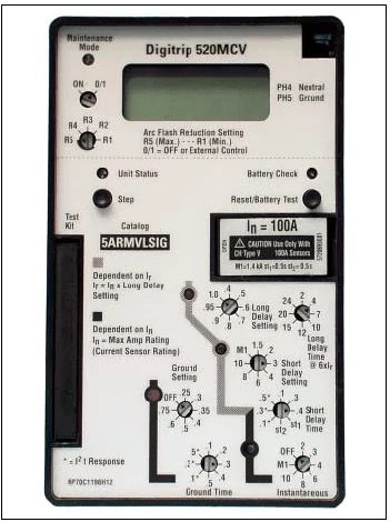
Setting an arc flash reduction maintenance system in circuit breakers
By performing the arc flash study on the system, the incident energy (calories/cm2) and fault clearing time can be found. Now, consider the cases in which fault clearing time is longer than 2 seconds. As arc duration of 2 seconds is assumed to determine the incident energy according to IEEE Standard 1584-2018. After short listing such cases, the lowest arcing fault current needs to be considered for setting your maintenance mode switch. Make sure that the lowest arcing fault found in your system comes under the instantaneous region of circuit breaker in maintenance mode.
Modelling arc flash reduction maintenance system of circuit breaker using ETAP
System Overview:
The system consist of utility supply, which provides a fault current of 20kA. Protecting the downstream panels, we have our primary line of defense: the Main Circuit Breaker(Main CB), with an interrupting rating of 65kA. The Main Circuit Breaker feeds the panels named as Panel A and Panel B with their respective connected circuit breakers FDR PNL A and FDR PNL B. Considering, these panels house critical loads that need to be safeguarded during both routine operations and maintenance activities.

Utility, Fault current 20KA.
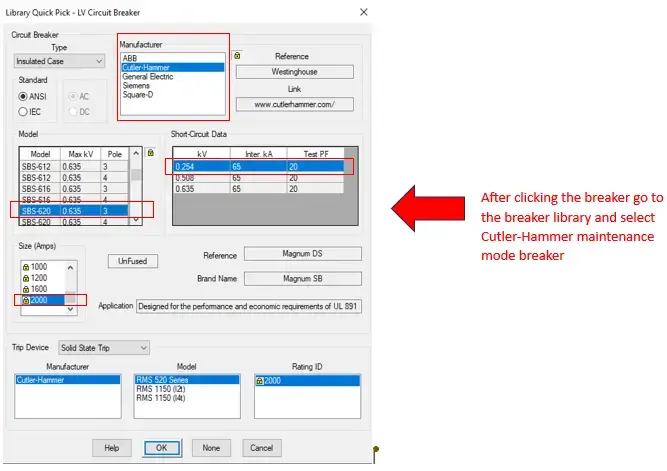
Cuttler Hammer, Circuit Breaker (Main CB).
Cuttler Hammer, Circuit Breaker (FDR PNL A and FDR PNL B).
Maintenance mode settings
Not all circuit breakers are equipped with maintenance mode settings. It's important to recognize that the availability of maintenance mode is often specific to certain models and provided by the Original Equipment Manufacturer (OEM).
circuit breakers with maintenance mode settings tend to be more expensive than their counterparts without this feature. This cost difference is attributed to the additional technology and engineering required to implement and ensure the reliability of maintenance mode functionalities.
Here is how you can select the circuit breaker in our model that you'd like to have the maintenance mode feature for, and then follow these steps.
Scenario:
Normal Utility Scenario (Maintenance Switch is Off):
In our SLD, the initial scenario shows utility operations, under regular conditions. However, this standard operation shows relatively high incident energy levels and longer fault clearing times, which can be dangerous for personnel conducting maintenance or repairs.
As We can see that when we run ARC FLASH in this senario here at PNL A and PNL B both have Incident Energy as “34 cal/cm2” and our Fault clearing time (FCT) is “ 2 sec”. ”

Maintenance Mode Scenario (Maintenance Switch is On):
By adding maintenance mode switches, we can enhance safety. When these switches are activated, they effectively isolate Panel A and Panel B from the main circuit, reducing incident energy and shortening fault-clearing times.
In this mode, the breaker prioritizes rapid fault clearance with an instantaneous response, bypassing certain time delays present in its normal operation. This adjustment significantly reduces the duration of arcing events, ensuring fast interruption of fault currents.

Consequently, the shorter arcing duration results in lower incident energy. By minimizing downtime and mitigating potential hazards, the maintenance mode Main CB creates a safer working environment for personnel involved in electrical system maintenance or repair.
As we can see that when we run ARC FLASH in this senario here at PNL A and PNL B both have Incident Energy as “0.863 cal/cm2” and our Fault clearing time (FCT) is “0.05 sec”.


Comments