

Fundamental Overcurrent, Distance and Differential Protection Principles
- Hüseyin GÜZEL

- Feb 11, 2024
- 6 min read
Essential Protection Principles

This technical article covers the four fundamental protection principles: Overcurrent, Directional Overcurrent, Distance and Differential. Overcurrent Protection guards against excessive current, Distance Protection safeguards transmission lines by estimating fault distance, and Differential Protection ensures internal fault detection in equipment. These protection principles collectively contribute to the reliability and stability of power systems by swiftly identifying and isolating faults.
Principle of overcurrent protection
Principle of directional overcurrent protection
Principle of distance protection
Principle of differential protection
For transmission line
For transformer
For busbar
For simplicity in explaining the key ideas, we consider three-phase bolted faults.
1| Overcurrent Protection
This scheme is based on the intuition that, faults typically short circuits, lead to currents much above the load current. We can call them overcurrents. Overcurrent relaying and fuse protection uses the principle that when the current exceeds a predetermined value, it indicates the presence of a fault (short circuit).
This protection scheme finds usage in radial distribution systems with a single source. It is quite simple to implement.

Figure 1 shows a radial distribution system with a single source. The fault current is fed from only one end of the feeder.
For this system, it can be observed that:
To relay R1, both downstream faults F1 and F2 are visible i.e. IF1, as well as IF2, pass through CT of R1.
To relay R2, fault F1, an upstream fault is not seen, only F2 is seen. This is because no component of IF1 passes through the CT of R2. Thus, selectivity is achieved naturally.
Relaying decision is based solely on the magnitude of fault current. Such a protection scheme is said to be non-directional.
2| Directional Overcurrent Protection
In contrast, there can be situations where for the purpose of selectivity, phase angle information (always relative to a reference phasor) may be required. Figure 2 shows such a case for a radial system with a source at both ends. Consequently, the fault is fed from both ends of the feeder.
To interrupt the fault current, relays at both ends of the feeder are required
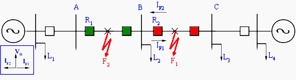
In this case, from the magnitude of the current seen by the relay R2, it is not possible to distinguish whether the fault is in section AB or BC. Since faults in section AB are not in its jurisdiction, it should not trip.
To obtain selectivity, a directional overcurrent relay is required. It uses both the magnitude of current and phase angle information for decision making. It is commonly used in sub-transmission networks where ring mains are used.
3| Distance Protection
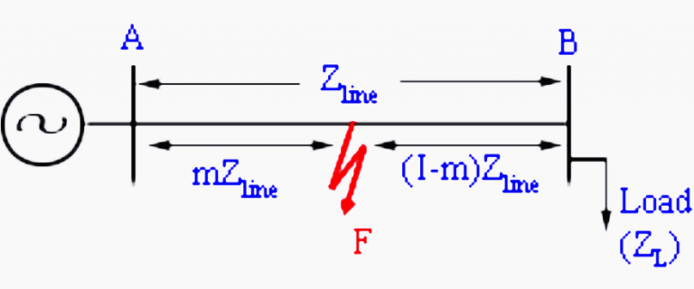
Consider a simple radial system, which is fed from a single source. Let us measure the apparent impedance (V/I) at the sending end.
For the unloaded system, I = 0, and the apparent impedance is seen by the relay is infinite. As the system is loaded, the apparent impedance reduces to some finite value (ZL+Zline) where ZL is the load impedance and Zline is the line impedance. In presence of a fault at a per-unit distance ‘m’, the impedance is seen by the relay drops to an mZ line as shown in figure 3 below.
The basic principle of distance relay is that the apparent impedance seen by the relay, which is defined as the ratio of phase voltage to line current of a transmission line (Zapp), reduces drastically in the presence of a line fault. A distance relay compares this ratio with the positive sequence impedance (Z1) of the transmission line. If the fraction Zapp/Z1 is less than unity, it indicates a fault. This ratio also indicates the distance of the fault from the relay.
Because, impedance is a complex number, distance protection is inherently directional. The first quadrant is the forward direction i.e. impedance of the transmission line to be protected lies in this quadrant.
However, if only magnitude information is used, non-directional impedance relay results. Figures 4 and 5 shows a characteristic of an impedance relay and ‘mho relay’ both belonging to this class.
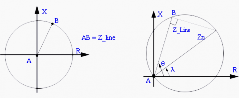
The impedance relay trips if the magnitude of the impedance is within the circular region. Since, the circle spans all the quadrants, it leads to a non-directional protection scheme. In contrast, the mho relay which covers primarily the first quadrant is directional in nature.
Thus, the trip law for the impedance relay can be written as follows:
|Zapp| = |VR| / |IR| < |Zset|
then trip; else restrain.
While impedance relay has only one design parameter, Zset; ‘mho relay’ has two design parameters Zn, λ. The trip law for mho relay is given by if:
|Zapp| < |Zn| cos (θ – λ)
then trip; else restrain.
As shown in Figure 5, θ is the angle of the transmission line. Based upon the legacy of electromechanical relays λ is also called ‘torque angle’
4| Principle of Differential Protection
Differential protection is based on the fact that any fault within electrical equipment would cause the current entering it, to be different, from the current leaving it.
Thus by comparing the two currents either in magnitude or in-phase or both we can determine a fault and issue a trip decision if the difference exceeds a predetermined set value.
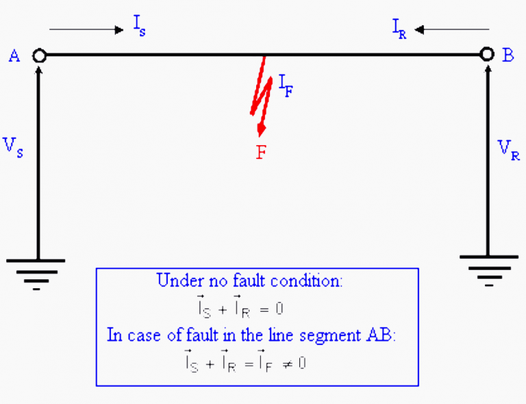
4.1| Differential Protection for Transmission Line
Figure 6 shows a short transmission line in which shunt charging can be neglected. Then under no-fault condition, the phasor sum of currents entering the device is zero i.e.
IS + IR = 0
Thus, we can say that the differential current under no-fault condition is zero. However, in case of a fault in the line segment AB, we get:
IS + IR = IF ≠ 0
i.e. differential current in presence of fault is non-zero.
This principle of checking the differential current is known as a differential protection scheme.
In the case of the transmission line, implementation of differential protection requires a communication channel to transmit current values to the other end. It can be used for short feeders and a specific implementation is known as pilot wire protection. Differential protection tends to be extremely accurate. Its zone is clearly demarcated by the CTs which provide the boundary.
Differential protection can be used for tapped lines (multiterminal lines) where boundary conditions are defined as follows:
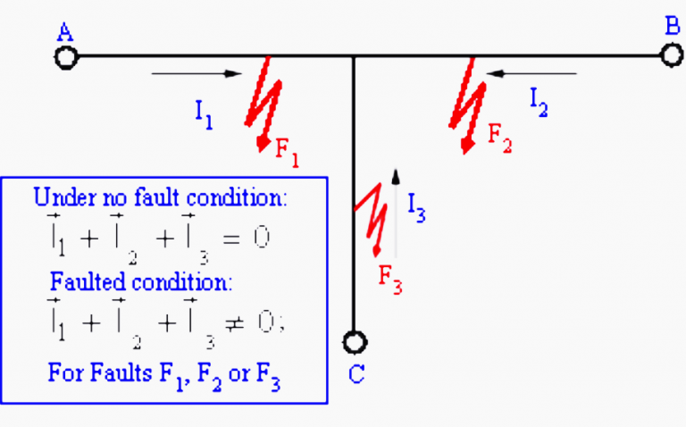
Under no-fault condition:
I1 + I2 + I3 = 0
Faulted condition:
I1 + I2 + I3 ≠ 0
4.2| Differential Protection for Transformer
Differential protection for detecting faults is an attractive option when both ends of the apparatus are physically located near each other. e.g. on a transformer, a generator or a bus bar.
Consider an ideal transformer with the CT connections, as shown in Figure 8.
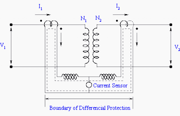
To illustrate the principle let us consider that the current rating of the primary winding is 100A and the secondary winding is 1000A. Then if we use 100:5 and 1000:5 CT on the primary and secondary winding, then under normal (no-fault) operating conditions the scaled CT currents will match in magnitudes. By connections the primary and secondary CTs with due care to the dots (polarity markings), a circulating current can be set up as shown by a dotted line.
No current will flow through the branch having an overcurrent current relay because it will result in a violation of KCL.
Now if an internal fault occurs within the device like inter-turn short etc., then the normal mmf balance is upset i.e. N1I1 ≠ N2I2. Under this condition, the CT secondary currents of primary and secondary side CTs will not match. The resulting differential current will flow through the overcurrent relay. If the pick upsetting of the overcurrent relay is close to zero, it will immediately pick up and initiate the trip decision.
In practice, the transformer is not ideal. Consequently, even if I2=0, I1≠0, it is the magnetization current or (no load) current. Thus, a differential current always flows through the overcurrent relay.
Therefore overcurrent relay picks up is adjusted above the no-load current value. Consequently, minute faults below the no-load current value cannot be detected. This compromises sensitivity.
4.3| Differential Protection for Busbar
Ideally, differential protection is the solution for busbar protection. Figure 9 illustrates the basic idea. If the fault is external to the bus, it can be seen that the algebraic sum of the currents entering the bus is zero.
IA + IB + IC + ID + IE = 0
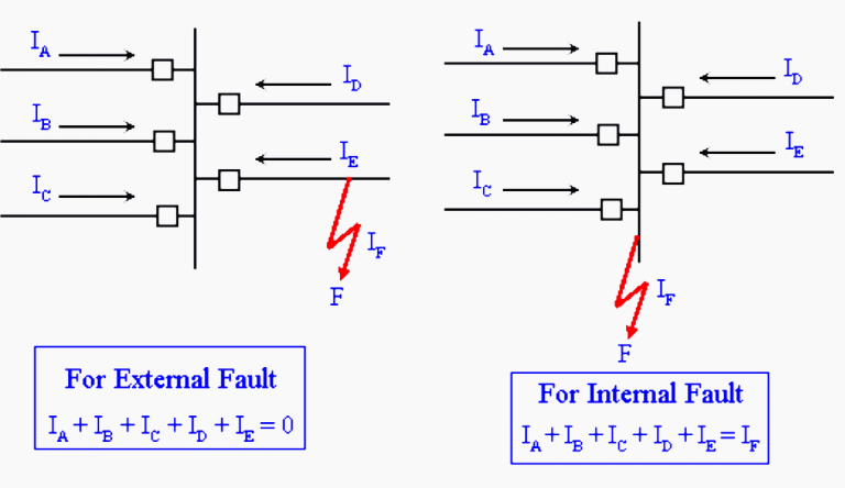
On the other hand, if fault is on the bus (internal fault), this sum is not zero.
IA + IB + IC + ID + IE = IF
Thus, differential protection can be used to protect a bus
Reference: Fundamentals of Power System Protection – Extract from IIT Bombay NPTEL
Lecture-1: http://wix.to/lu5hJoc
Lecture-2: http://wix.to/LRViakB
Lecture-3: http://wix.to/xPtrpeV
Lecture-4: http://wix.to/yhRnbph
Lecture-5: http://wix.to/x7z7EuX
Lecture-6: http://wix.to/NQgrbZN
Lecture-7: http://wix.to/sz38SgN
Lecture-8: http://wix.to/GYHXQit
Lecture-9: http://wix.to/2Z3n5bV
Lecture-10: http://wix.to/bUhL7y8
Lecture-11: http://wix.to/99MMu5u
Lecture-12: http://wix.to/s9RFITf
Lecture-13: http://wix.to/oVnJjoV
Lecture-14: http://wix.to/ibymB6V
Lecture-15: http://wix.to/1sHompw
Lecture-16: http://wix.to/kTCKQfx
Lecture-17: http://wix.to/DcFx8UV
Lecture-18: http://wix.to/PHIsHsN
Lecture-19: http://wix.to/lKXmlZS
Lecture-20: http://wix.to/Ax9kdDA
Lecture-21: http://wix.to/LncUcQF
Lecture-22: http://wix.to/FKHZUj9
Lecture-23: http://wix.to/Xx9Qlls
Lecture-24: http://wix.to/RTQwvcm
Lecture-25: http://wix.to/c5kIZLT
Lecture-26: http://wix.to/o9sEJfn
Lecture-27: http://wix.to/kZRms6Y
Lecture-28: http://wix.to/8ZhJmJt
Lecture-29: http://wix.to/oSA0Gt9
Lecture-30: http://wix.to/0cPblQ8
Lecture-31: http://wix.to/ccOFVsM
Lecture-32: http://wix.to/PCJyvSL
Lecture-33: http://wix.to/24uf5Gm
Lecture-34: http://wix.to/x06mvTg
Lecture-35: http://wix.to/3NPkjat
Lecture-36: http://wix.to/rRrvkqv
Lecture-37: http://wix.to/hWdDMex
Lecture-38: http://wix.to/6bt3RLn
Lecture-39: http://wix.to/0LJlGpO
Lecture-40: http://wix.to/POs4Nv7


Comments