
Calculate The Reactive Power of the Capacitor Bank and Improve PF by ABB
- Hüseyin GÜZEL

- Jan 11, 2024
- 3 min read
Dimensioning of the capacitor bank
For the dimensioning of the #capacitorbank to be installed in order to improve the #powerfactor of a plant, it is necessary to #calculate correctly the #power factor according to the consumption or to the #load cycle of the #plant. This in order to avoid the intake of excess #reactiveenergy, which is a condition normally forbidden by power supply authorities.
Warning: The content of this article is cited from the Power factor correction and harmonic filtering in electrical plants by #ABB
To carry out distributed or group power factor correction, it is necessary to calculate the cosφ of the single load or of the group of loads (factory areas).
This can be carried out as follows:
Directly – through direct measuring by means of a power factor meter
Indirectly – through the reading of the active and reactive energy meters
!!! The power factor meter is a measuring instrument able to display the power factor cosφ according to which the load is absorbing energy. The reading of the instrument shall be carried out in different moments of the load cycle, so that an average power factor value can be obtained.
If the readings of the active and reactive energy absorbed by the load or by the whole of the loads constituting the factory areas during a work cycle are available, the average power factor can be calculated as follows:
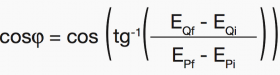
where:
EPi and EQi are the values of active and reactive energy read at the beginning of the work cycle
EPf and EQf are the values of active and reactive energy read at the end of the work cycle
Calculation of The Necessary Reactive Power
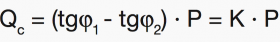
Once the power factor (cosφ1) of the installation and the power factor to be obtained (cosφ2) are known, it is possible to calculate the reactive power of the capacitor bank necessary to improve the power factor.
Indicating by:
P – the installed active power
φ1 – the phase displacement angle before power factor correction
φ2 – the phase displacement angle to be obtained with the power factor correction the power of the capacitor bank Qc is:
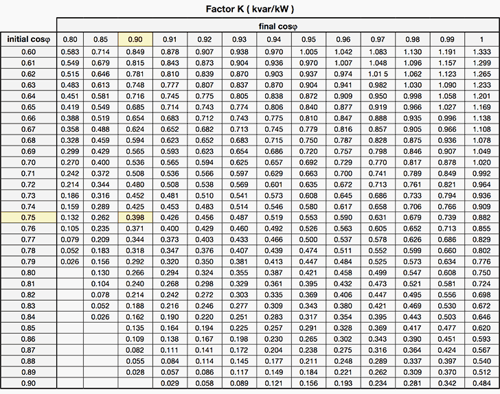
Once the initial cosφ is known, Table 1 allows to calculate (in kvar per kW installed) the power of the capacitor bank necessary to obtain a defined power factor.
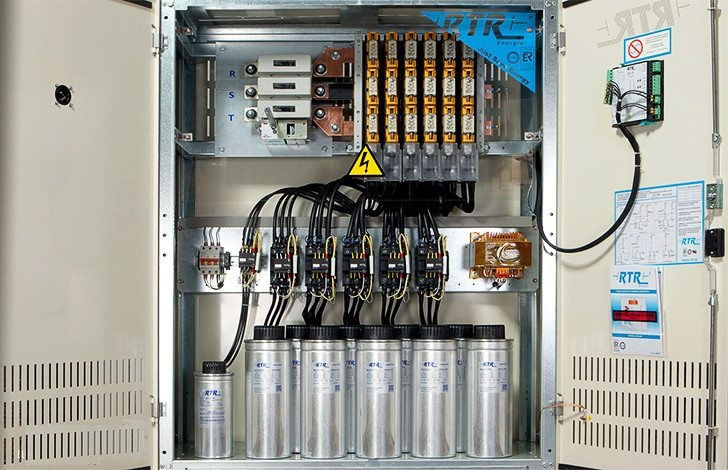
I!! In a three-phase system, the capacitor bank constituted by three capacitors having the same capacitance, can be delta connected or star connected.
When selecting the connection modality, it is necessary to keep into account that with a delta connection, each capacitance is subject to the supply line-to-line voltage, but, at the same level of generated reactive power, it has a value equal to 1/3 of the value it will have in case of star-connection:
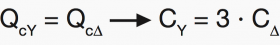

In the low voltage field, where insulation problems are less important, the delta connection is usually preferred for the capacitor bank, since it allows a smaller sizing of the capacitances of each phase
Example calculation
In a plant with active power equal to 300 kW at 400 V and cosφ= 0.75, we want to increase the power factor up to 0.90. In the table 1 above, at the intersection between the row “initial cosφ” 0.75 with the column “final cosφ” 0.9, a value of 0.398 for the coefficient K is obtained.
Therefore a capacitor bank is necessary with power Qc equal to:
Qc = K · P = 0.398 · 300 = 119.4 kvar
The factor K can be determined also using the following nomograph:
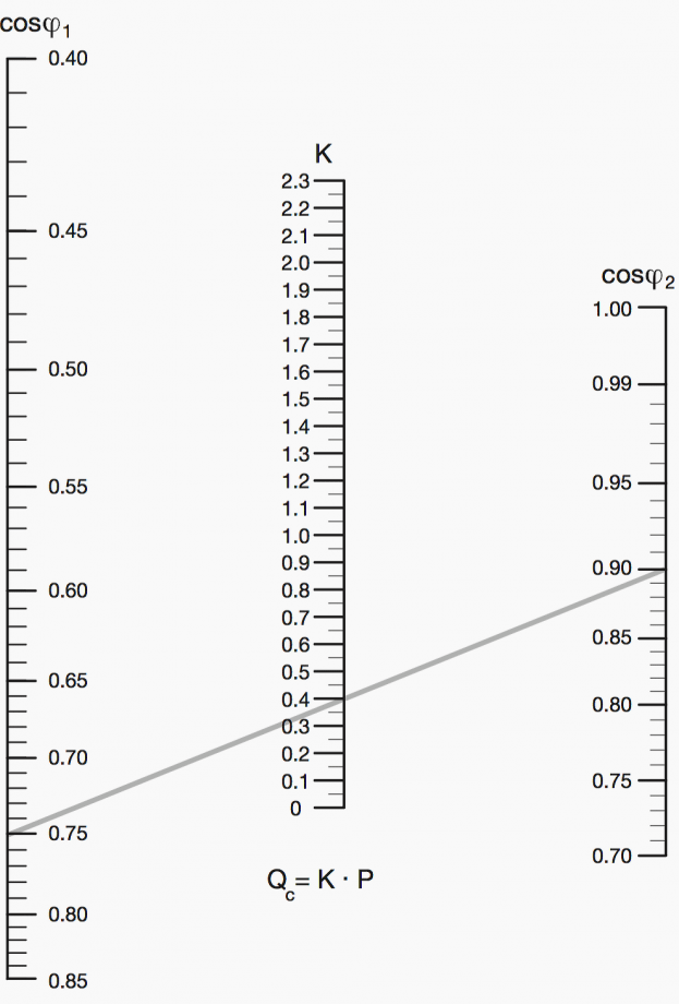
As shown in the figure, tracing a line segment from the value of the initial cosφ to the value to be obtained, the intersection of the line with the middle graduated scale, gives the value of K which, multiplied by the active power P of the load, defines the necessary reactive power Qc.


KING88 – sân chơi cá cược đỉnh cao, minh bạch, uy tín. Thể thao, casino, bắn cá, lô đề cực hot. Truy cập king88vn shop để nhận thưởng lớn và trải nghiệm không giới hạn!
789WIN – Cổng game trực tuyến đa nền tảng, mang lại trải nghiệm đỉnh cao. Mỗi trò chơi đều được thiết kế minh bạch và tối ưu hóa. Truy cập và thử vận may tại https://789winv.me/
Nhà cái uy tín mang đến sự minh bạch, uy tín và lợi ích tối đa cho người tham gia cá cược đổi thưởng trực tuyến. https://nhacaiuytin.now/
789Win mang đến những giây phút cá cược sôi động, công bằng và cơ hội thắng lớn. Đăng nhập ngay để nhận nhiều ưu đãi tại https://789win.br.com/
jun88 nổi bật với những chương trình khuyến mãi hấp dẫn: tặng thưởng tân thủ, hoàn trả không giới hạn và hàng loạt ưu đãi đặc biệt. Để không bỏ lỡ, hãy theo dõi jun88 travel – nơi cập nhật thông tin khuyến mãi chính thức và đầy đủ nhất.